Welcome to YUSH Electronic Technology Co.,Ltd.
YUSH Electronic
  English    Chinese
News
Mounter operation and description

note:
1) Grasp the name of each component and compare it to the actual object of the machine to indicate the name and basic functionality of the component.
2) Which button should be pressed in the event of an emergency, the status of the warning light and the display of the operation display?


note:
a) Unauthorized personnel are strictly prohibited from operating the machine.
b) The operating equipment must be safe first. The machine operator should operate the machine in strict accordance with the operating specifications. Otherwise, the machine may be damaged or compromised.
c) The machine operator should be careful.
Fourth, the name and function of each part of the placement machine
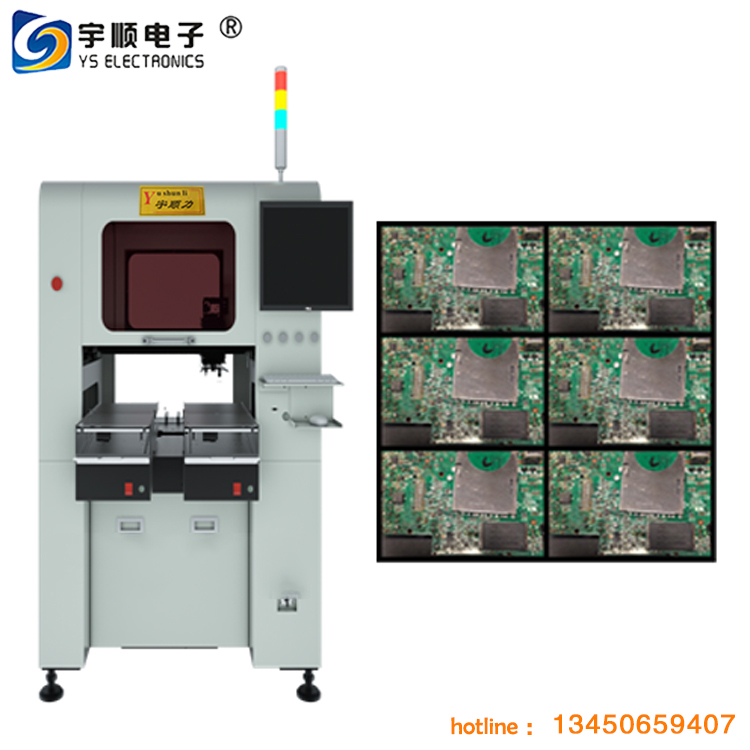
host
1.1 Main power switch: turn main power on or off
1.2 Visual Monitor: Displays images or components obtained by moving the lens and symbol recognition.
1.3 Operation Monitor: Displays the VIOS software screen for machine operation. If an error or problem occurs during the operation, the calibration information will also be displayed on the screen.
1.4 Warning Light: Indicates the working status of the placement machine in green, yellow and red.
Green: The machine is in automatic operation
Yellow: Error (cannot perform return to origin, pick error, identify fault, etc.) or generate an interlock.
Red: The machine is in an emergency stop (press the machine or the YPU stop button).
1.5 Emergency stop button: Press this button to trigger an emergency stop immediately.
2. Head assembly
Work head assembly: Move in the XY direction (or X direction), pick up parts from the feeder and mount them on the PCB.
Movement handle: After releasing the servo controller, you can move in all directions with your hands. This handle is typically used when moving the work head assembly by hand.
3. Visual system
Mobile camera: Used to identify markers or position or coordinate tracking on the PCB.
Single Vision Camera: Used to identify components, primarily components with pins.
Backlight unit: Illuminates the component from the back when it is recognized by a separate vision lens.
Laser unit: The laser beam can be used to identify parts, mainly sheet parts.
Multi-Vision camera: Accelerate recognition by identifying multiple parts at once.
4. Feeding platform (FeederPlate):
Use feeders, bulk feeders and tube feeders (multi-tube feeders) that can be mounted on the front or rear feed platform of the placement machine.
5. Axis configuration
X-axis: The moving head assembly is parallel to the PCB transfer direction.
Y-axis: The moving head assembly is perpendicular to the PCB transfer direction.
Z-axis: Controls the height of the work head assembly.
R-axis: Controls the rotation of the nozzle axis of the working head assembly.
W axis: Adjust the width of the transport rail.
6. Conveying unit
1, the main stopper (Main Stopper)
2, positioning pin (Locate Pins)
3, push unit (in the push component)
4, edge clip (Edge Clamp)
5, Push-up Plate (Push-up Plate)
6, Push-up Pins
7. Entrance plug (inlet plug)
7. Nozzle station: Allows automatic nozzle replacement, a total of 16 nozzles, 7 standard nozzles and 9 optional nozzles.
8. Gas supply unit
Includes air filter, air pressure adjustment button, barometer.


Getting started knowledge


As a high-tech product, the placement machine is safe and correct for both the machine and the personnel.

The most basic thing to safely operate the placement machine is that the operator should make the most accurate judgment. The following basic safety rules should be followed:
1. The machine operator should receive operational training in the correct manner.
2. When checking the machine, replacing parts, or performing maintenance and internal adjustments, turn off the power (you must use the emergency button to service the machine or turn off the power).
3. Make sure to stop the machine at any time using Read Coordinates and YPU (Programming Unit).
4. Make sure that the “interlocking” safety device is always active to stop the machine at any time. Safety tests on the machine cannot be skipped or shorted, otherwise personal or machine safety incidents may occur.
5. Only one operator is allowed to operate one machine during the production process.
6. During operation, certain parts of the body (such as the hands and head) are indeed out of range of machine motion.
7. The machine must be properly grounded (correctly grounded, not neutral).

8. Do not use the machine in a gas or extremely dirty environment.


Product Categories
                                                  Location: Home -> News

                                                  Mounter operation and description


                                                  note:
                                                  1) Grasp the name of each component and compare it to the actual object of the machine to indicate the name and basic functionality of the component.
                                                  2) Which button should be pressed in the event of an emergency, the status of the warning light and the display of the operation display?


                                                  note:
                                                  a) Unauthorized personnel are strictly prohibited from operating the machine.
                                                  b) The operating equipment must be safe first. The machine operator should operate the machine in strict accordance with the operating specifications. Otherwise, the machine may be damaged or compromised.
                                                  c) The machine operator should be careful.
                                                  Fourth, the name and function of each part of the placement machine
                                                  host
                                                  1.1 Main power switch: turn main power on or off
                                                  1.2 Visual Monitor: Displays images or components obtained by moving the lens and symbol recognition.
                                                  1.3 Operation Monitor: Displays the VIOS software screen for machine operation. If an error or problem occurs during the operation, the calibration information will also be displayed on the screen.
                                                  1.4 Warning Light: Indicates the working status of the placement machine in green, yellow and red.
                                                  Green: The machine is in automatic operation
                                                  Yellow: Error (cannot perform return to origin, pick error, identify fault, etc.) or generate an interlock.
                                                  Red: The machine is in an emergency stop (press the machine or the YPU stop button).
                                                  1.5 Emergency stop button: Press this button to trigger an emergency stop immediately.
                                                  2. Head assembly
                                                  Work head assembly: Move in the XY direction (or X direction), pick up parts from the feeder and mount them on the PCB.
                                                  Movement handle: After releasing the servo controller, you can move in all directions with your hands. This handle is typically used when moving the work head assembly by hand.
                                                  3. Visual system
                                                  Mobile camera: Used to identify markers or position or coordinate tracking on the PCB.
                                                  Single Vision Camera: Used to identify components, primarily components with pins.
                                                  Backlight unit: Illuminates the component from the back when it is recognized by a separate vision lens.
                                                  Laser unit: The laser beam can be used to identify parts, mainly sheet parts.
                                                  Multi-Vision camera: Accelerate recognition by identifying multiple parts at once.
                                                  4. Feeding platform (FeederPlate):
                                                  Use feeders, bulk feeders and tube feeders (multi-tube feeders) that can be mounted on the front or rear feed platform of the placement machine.
                                                  5. Axis configuration
                                                  X-axis: The moving head assembly is parallel to the PCB transfer direction.
                                                  Y-axis: The moving head assembly is perpendicular to the PCB transfer direction.
                                                  Z-axis: Controls the height of the work head assembly.
                                                  R-axis: Controls the rotation of the nozzle axis of the working head assembly.
                                                  W axis: Adjust the width of the transport rail.
                                                  6. Conveying unit
                                                  1, the main stopper (Main Stopper)
                                                  2, positioning pin (Locate Pins)
                                                  3, push unit (in the push component)
                                                  4, edge clip (Edge Clamp)
                                                  5, Push-up Plate (Push-up Plate)
                                                  6, Push-up Pins
                                                  7. Entrance plug (inlet plug)
                                                  7. Nozzle station: Allows automatic nozzle replacement, a total of 16 nozzles, 7 standard nozzles and 9 optional nozzles.
                                                  8. Gas supply unit
                                                  Includes air filter, air pressure adjustment button, barometer.


                                                  Getting started knowledge


                                                  As a high-tech product, the placement machine is safe and correct for both the machine and the personnel.

                                                  The most basic thing to safely operate the placement machine is that the operator should make the most accurate judgment. The following basic safety rules should be followed:
                                                  1. The machine operator should receive operational training in the correct manner.
                                                  2. When checking the machine, replacing parts, or performing maintenance and internal adjustments, turn off the power (you must use the emergency button to service the machine or turn off the power).
                                                  3. Make sure to stop the machine at any time using Read Coordinates and YPU (Programming Unit).
                                                  4. Make sure that the “interlocking” safety device is always active to stop the machine at any time. Safety tests on the machine cannot be skipped or shorted, otherwise personal or machine safety incidents may occur.
                                                  5. Only one operator is allowed to operate one machine during the production process.
                                                  6. During operation, certain parts of the body (such as the hands and head) are indeed out of range of machine motion.
                                                  7. The machine must be properly grounded (correctly grounded, not neutral).

                                                  8. Do not use the machine in a gas or extremely dirty environment.


                                                  YUSH Electronic Technology Co.,Ltd. Pomeas Optical Technology Copyright 2016
                                                  CONTACT US

                                                  Website:https://www.pcbcuttingmachine.com
                                                  Contacts:Eva Liu +8613450659407 +8613416743702
                                                  Tel:+86-512-62751429
                                                  Skype:evaliuhuan
                                                  Email:caojun@hk-yush.com  sales@yushunli.com evaliu@hk-yush.com
                                                  Address: Building H, GuoRui Pioneering Park,
                                                  No. 1068 Jinyang East Road, Lujia Town, Kunshan,Suzhou.
                                                  Postcode:215331
                                                  Dongguan Factory Address: 5th Floor, No.10,
                                                  Shanquan Road, Yongtou Village, Chang’an Town,
                                                  Dongguan City, Guangdong province, China.
                                                  Postcode:523843

                                                  YUSH Electronic Technology Co.,Ltd. Pomeas Optical Technology Copyright 2016