9, the shield cover placement machine can be changed to the use of special-shaped components plug-in machine
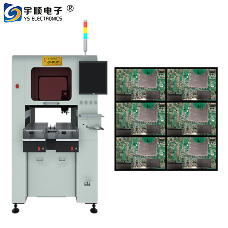
Introduction to the principle of SMT component placement machine
The process of accurately placing the SMC/SMD on the PCB and printing the corresponding position on the surface of the solder paste or the adhesive is called the placement (sMD) process. In the current domestic electronic product manufacturing enterprises, automatic placement machines are mainly used for automatic placement, and manual placement is also possible. Manual patches are now commonly used in repair or small batch production.
Introduction to the principle of SMT component placement machine
To ensure the quality of the patch, three factors should be considered: the correctness of the mounted components, the accuracy of the placement position, and the appropriateness of the placement pressure (patch height). Requirements for placement components in the placement process:
1. The type, type, nominal value and polarity of the component should be in accordance with the requirements of the product assembly drawing and the schedule.
2. The thickness of the soldered end or pin on the mounted component should be immersed in the solder paste. When the component is mounted on the chip, the solder paste should be less than 0.2mm; the solder paste of the narrow pitch component should be squeezed. The output should be less than 0.1mm.
3. The solder joints or pins of the components should be aligned and centered as much as possible on the land pattern. Because of the self-positioning effect during reflow soldering, the placement position of the components allows a certain deviation.
4. The component mounting pressure should be suitable. If the pressure is too small, the soldering end or pin of the component will float on the surface of the solder paste, so that the solder paste can not stick to the component, and may be in the process of transfer and reflow soldering. Produce positional movement.
5. If the component mounting pressure is too large, the solder paste extrusion amount is too large, which is easy to cause the solder paste to overflow and stick, which causes bridging during reflow soldering, and also causes the sliding deviation of the device, which may damage the device in severe cases.


9, the shield cover placement machine can be changed to the use of special-shaped components plug-in machine
Introduction to the principle of SMT component placement machine
The process of accurately placing the SMC/SMD on the PCB and printing the corresponding position on the surface of the solder paste or the adhesive is called the placement (sMD) process. In the current domestic electronic product manufacturing enterprises, automatic placement machines are mainly used for automatic placement, and manual placement is also possible. Manual patches are now commonly used in repair or small batch production.
Introduction to the principle of SMT component placement machine
To ensure the quality of the patch, three factors should be considered: the correctness of the mounted components, the accuracy of the placement position, and the appropriateness of the placement pressure (patch height). Requirements for placement components in the placement process:
1. The type, type, nominal value and polarity of the component should be in accordance with the requirements of the product assembly drawing and the schedule.
2. The thickness of the soldered end or pin on the mounted component should be immersed in the solder paste. When the component is mounted on the chip, the solder paste should be less than 0.2mm; the solder paste of the narrow pitch component should be squeezed. The output should be less than 0.1mm.
3. The solder joints or pins of the components should be aligned and centered as much as possible on the land pattern. Because of the self-positioning effect during reflow soldering, the placement position of the components allows a certain deviation.
4. The component mounting pressure should be suitable. If the pressure is too small, the soldering end or pin of the component will float on the surface of the solder paste, so that the solder paste can not stick to the component, and may be in the process of transfer and reflow soldering. Produce positional movement.
5. If the component mounting pressure is too large, the solder paste extrusion amount is too large, which is easy to cause the solder paste to overflow and stick, which causes bridging during reflow soldering, and also causes the sliding deviation of the device, which may damage the device in severe cases.
Website:https://www.pcbcuttingmachine.com
Contacts:Eva Liu +8613450659407 +8613416743702
Tel:+86-512-62751429
Skype:evaliuhuan
Email:caojun@hk-yush.com sales@yushunli.com evaliu@hk-yush.com
Address: Building H, GuoRui Pioneering Park,
No. 1068 Jinyang East Road, Lujia Town, Kunshan,Suzhou.
Postcode:215331
Dongguan Factory Address: 5th Floor, No.10,
Shanquan Road, Yongtou Village, Chang’an Town,
Dongguan City, Guangdong province, China.
Postcode:523843